Here is a listing of parts I used. . I will try to associate each build stage with the parts if they are unique for latter stages. Base parts are a music player that will play automatically when you start the game, play random songs on the sd card, and then turn off when the game is done. Also are sound effects from the second mp3 player. (note: you could just make a simple music player off an Arduino and when i get time i will make one but for only a little more I recommend the Arduino Mega as it’s has more potential. Scoring is to get a Bluetooth module that sends the score to a smart phone app.I made. Scoring is still underdevelopment but if you are ok with scores not matching the reels at times its ok as it then allows you to add new rules such as hurry ups. Mounting are items that are associated with fitting everything inside the pinball machine. Toppers are items that allow one to add a dynamic topper that can react to the game conditions.. Power options are multiple where one could tap off the machine and install an outlet, run power from its own outlets or even from a computer. There are pros and cons for each but all in all you really cant go wrong. . There is also means to potentially add video display, lighting, that go beyond what has been developed so far. If you know of a better component to use, please share in the forum
I am also listing some of the tools I am using or recommend but most likely you may already have most of them as it doesn’t need much. Right now my criteria is “did they work” and that is about it. This is the latest parts list. I apologize for the formatting on some line items but i cannot get some items to align properly.
| item | link | Description | qty | price | Total |
|---|---|---|---|---|---|
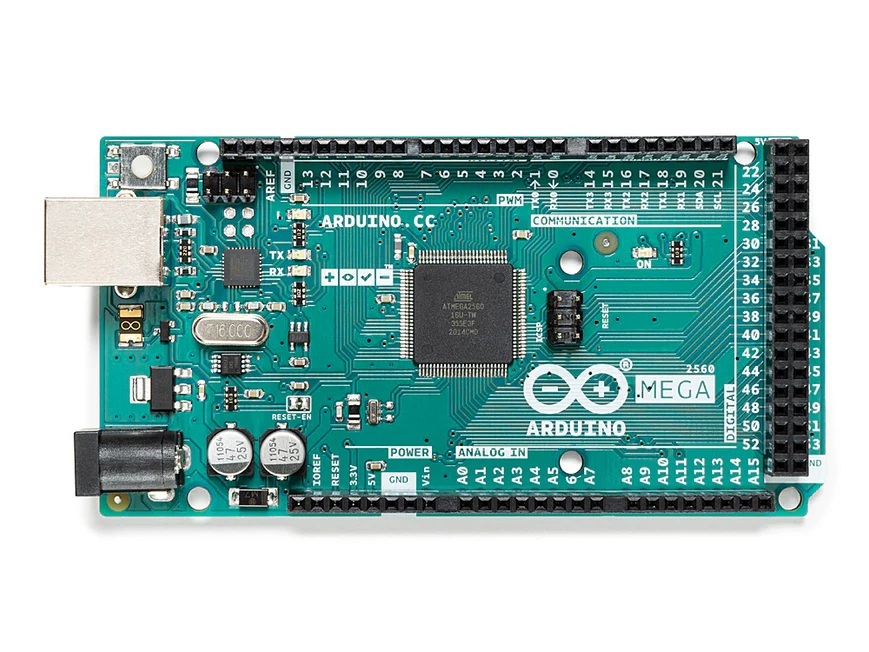
| base | https://amzn.to/3O3RPVq | Arduinio Mega Board | 1 | 22.99 | $22.99 |
| base | https://amzn.to/4sb4oxB | Mega Sheild | 1 | 8.99 | $8.99 |
| base | https://amzn.to/4j0RwWs | power cord for Mega | 1 | 7.49 | $7.49 |
| base | https://amzn.to/4aoogXt | hall magnetic sensor | 1 | 5.99 | $5.99 |
| base | https://amzn.to/4j4kjt9 | set of led lights sets 1 | 9.99 | $9.99 | |
| base | https://amzn.to/4lUjepb | set of light sensors 1 6.99 | $6.99 | ||
| base | https://amzn.to/4dcGM6G | long wire sets | 1 | 19.99 | $19.99 |
| base | https://amzn.to/4szkyQS | header pins | 1 | 5.49 | $5.49 |
| base | https://amzn.to/4uYLCu I | sound module leads | 1 | 10.39 | $10.39 |
| base | https://amzn.to/4lPeHEw | sound module boards | 2 | 9.99 | $19.98 |
| base | https://amzn.to/3NqAPso | small speakers | 2 | 9.99 | $19.98 |
| base | https://amzn.to/4lQMywR | 32mb sd card set of (3) | 1 | 25.99 | $25.99 |
| base | https://amzn.to/4lQMWvj | Extension to speakers | 2 | 4.99 | $9.98 |
| base | https://amzn.to/4bON7Tr | power strip | 1 | 9.49 | $9.49 |
| base | https://amzn.to/4dUDy7U | female dupont wires | 2 | 3.99 | $7.98 |
| sub total | $168.72 | ||||
| mounting | https://amzn.to/4sunkXI | dressing kit for wires | 1 | 14.99 | $14.99 |
| mounting | https://amzn.to/41rBZHg 3M double sided tape1 | 8.99 | $8.99 | ||
| mounting | https://amzn.to/4sIulEE | piano wire 1 | 9.99 | $9.99 | |
| mounting | https://amzn.to/3PLJhmx | heat shrink tubing | 1 | 13.99 | $13.99 |
| sub total | $47.96 | ||||
| scoring | https://amzn.to/4tflPwE | bluetooth modules set of (2) | 1 | 10.59 | $10.59 |
| topper | https://amzn.to/4v1IcHF | disco ball topper | 1 | 23.99 | $23.99 |
| topper | https://amzn.to/3NZsH29 | Arduino relay | 1 | 36.25 | $36.25 |
| topper | https://amzn.to/47prIPi | extension cord for OT relay | 1 | 3.70 | $3.70 |
| sub total | $63.94 | ||||
| total | $291.21 | ||||
| optional | https://amzn.to/4p1vp3K | infrared sensor set | 1 | 8.79 | $8.79 |
| optional | https://amzn.to/4bON7Tr | low cost laptop 1 | 174.88 | $174.88 |
i had trouble showing everything but here is the same info with active links to make it easier.
Notes on items used
If at times may have some completed units for sale. please email me at emsfx1@gmail-com if you want to go that route.
Note We use the Arduino Mega because it has lots of pins and can run two mp3 players simultaneously
Arduino Mega’s Shield. A Shield goes over the mega, reverses the pins to females, and make them easier to access.
the Mega can get its power from the computer’s usb but for in the field operation you will need a power cord
Next up is sensors. There are a lot of different sensors you can use. There are Hall sensors which detect magnetic fields in solenoids and motors, Light sensors that tell when a bulb is on or off, (infrared(?) or motion sensors that detect motion, , Voltage/optocoupler sensor to detect switches or solenoids going on or off. I am learning new ways to detect things and there may be others as well. Pretty much the theory of operation is the MEga’s sensor detects something and then the Mega does something like play a sound, add a score, start a timer etc
An optocoupler sensor is used to monitor when a leaf switch or even a solenoid is activated. Notice the voltage as you need to go from 24Vish to down to 5v for the arduino. https://amzn.to/48ZWyxI. There is also a trick to reverse the wiring to have the sensor go behave like the other sensors. These are the only sensors that I found that need soldering to the machine.
These are not sensors but when you find that its hard to mount a light sensor and get a clear view of the bulb, you solder an extension to the bulb and light these up when the bulb is on and then detect it with an light sensor https://amzn.to/4j4kjt9, These are also used as dynamic lighting and flashing for hurry ups.
You are going to need wires to connect everything. I want to have all end males with female ended wires. I did used male to female wires for longer runs but shorter female to female at the arduino. Lengths can vary as well so just get a bunch of different sizes and lengths. Roughly measure where your source is to your arduino and account for twist and turns.. Try to keep the same color for each wire run else you will go crazy. Also pay attention to the sensor’s pin order as they are not always the same order as on the Arduino. Sometimes the pins locations will cross each other in order to connect the voltage, ground and sensor signal
- Now if you haven’t figured it out yet you can actually build quite a number of systems if you buy a kit to get started.
i used a 3d printer to make the Mega’s angled mounting base
General Tools- Here are a listing of some tools one needs. They are basic solders things. Now I didn’t have any laptop at the time so I got the least expensive I could find. As my development pinball machine was outside my home, I needed to build and bench test the system on my desk but then when trying things out in the field I would need a display to see what the arduino is doing and sensing in the on the machine. You just need something to download code into your arduino from that can get close to your pinball machine.
Here is link for a solder iron kit https://amzn.to/3LbyVul
Here is a link to a low cost laptop. https://amzn.to/4pHIuQF
Lastly speakers are very open ended. I started using a pair from Goodwill,. Perhasp one day we can figure out how to go down to one pair of speakers but being so inexpensive, it may not be worth the effort.
There are other items that are still being investigated. If somebody would like to attempt to utilize these and let us know how they work out, it would be very interesting.
link to esp32 https://amzn.to/3KZdLzA
If you just wanted to add the music sound track and don’t need to run sound effects or do crazy scoring then you go go this route. My limited understanding is that an Arduino uno can only do one thing, as it has one set of transaction pins (TX1 ,Rx1) while the Mega has 3 sets (and doesn’t cost lot more) but sometimes KISS philosophy is better. https://amzn.to/496uitD
For the sound modules. the selector pins are set at 1 down 2 down 3 up
Here is a link to cable management accessories to help the install look nice. https://amzn.to/4rjDli1